
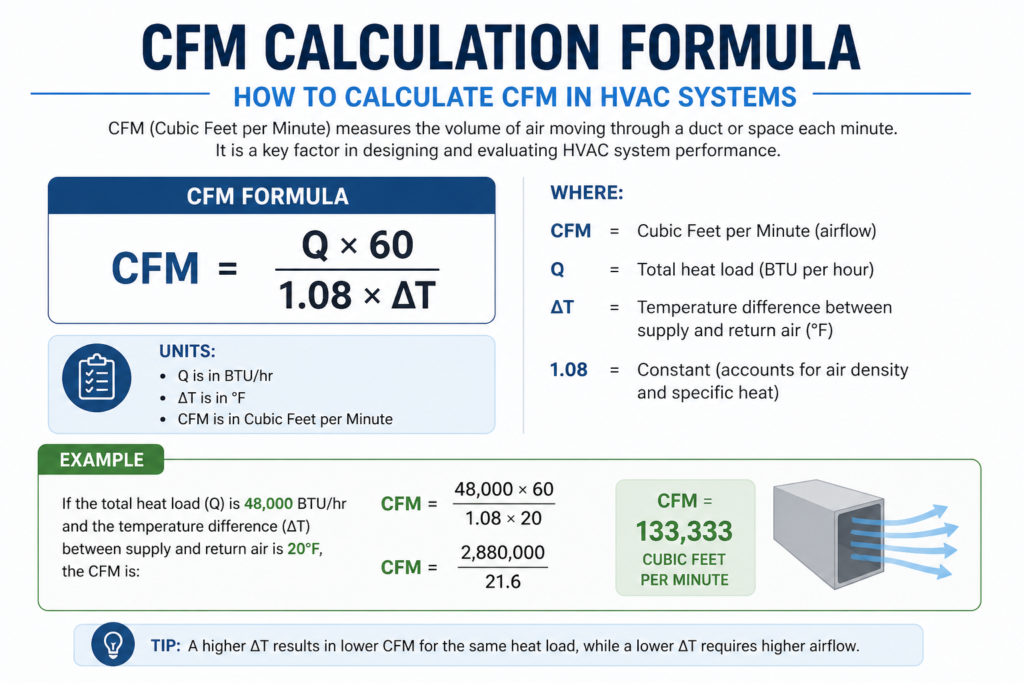
Quick answer: CFM stands for cubic feet per minute, the volume of air that moves through a duct or space each minute. To calculate it, multiply air velocity in feet per minute by the duct cross-section area in square feet (CFM = velocity x area). For room ventilation, use CFM = (room volume in cubic feet x air changes per hour) / 60. One CFM is about 1.7 cubic metres per hour.
Last updated: 15 November 2026
Key highlights for CFM Calculation
1. CFM Defined and Its Importance CFM (Cubic Feet per Minute) measures how much air moves through an HVAC system per minute. Matching the right CFM to a space is critical, an undersized system won’t heat/cool effectively, while an oversized one wastes energy through short cycling.
2. Two Core Methods to Calculate CFM The article outlines two approaches: (a) using room volume and air changes per hour (ACH), CFM = (Length × Width × Height × ACH) / 60, and (b) using system tonnage, CFM = Tonnage × 400, the industry standard rule of thumb.
3. CFM Varies by Room Size and Usage Different spaces need different airflow levels. A 100 sq ft room needs ~27 CFM at 2 ACH, while a 2,000 sq ft house needs ~533 CFM. High-risk spaces like kitchens or labs require more frequent air changes, directly increasing CFM requirements.
4. Duct Sizing Must Match CFM Duct diameter directly impacts delivered airflow. For example, a 10-inch flex duct handles 300 CFM, while a 20-inch duct handles 1,875 CFM. Choosing the wrong duct size bottlenecks the entire HVAC system.
5. Higher CFM Isn’t Always Better The article emphasizes balance over maximizing airflow. Too much CFM causes noise, poor humidity control, and short cycling, while too little leads to uneven cooling and frozen coils. The ideal CFM must be matched precisely to the system, space, and climate conditions.
Introduction
People have questions that they are buying the right HVAC system. Is it going to fit correctly? Here the role of CFM comes in.
HVAC technicians measure airflow using cubic feet per minute or a CFM calculator. It is to match the size of an HVAC system to the space or building. If it requires 1200 CFM, then a 3-ton HVAC system is good. Take the support of a leading HVAC company in India.
What is CFM?
CFM, or Cubic Feet per Minute, is a unit for airflow calculation in HVAC. The contractors calculate CFM for a room for air purifiers, fans, and such.
CFM Full Form in HVAC
Cubic Feet per Minute (CFM) is a unit that measures how much air or gas moves through a system in one minute. It is widely used in HVAC, ventilation, exhaust, and industrial equipment to evaluate airflow efficiency. A higher CFM means greater air-moving capacity, which is essential for cooling, heating, ventilation, and maintaining air quality.
For unit conversions, the heat-transfer forms of the formula and the codes that set CFM requirements, read our CFM full form guide.
Example:
- A 400 CFM exhaust fan moves 400 cubic feet of air every minute, making it suitable for kitchens or workshops.
- Large industrial blowers may deliver 10,000+ CFM, ensuring proper air circulation in factories or warehouses.
CFM (Cubic Feet per Minute) Comparison Table
| CFM Range | Airflow Capacity | Typical Applications |
| 50 – 200 CFM | Low airflow | Bathroom exhaust fans, small kitchen hoods, personal air purifiers |
| 200 – 500 CFM | Moderate airflow | Residential kitchens, small offices, retail shops |
| 500 – 2,000 CFM | High airflow | Large commercial kitchens, gyms, medium-sized workshops |
| 2,000 – 10,000 CFM | Very high airflow | Industrial HVAC units, warehouses, factories |
| 10,000+ CFM | Ultra-high airflow | Large manufacturing plants, pharma cleanrooms, heavy industrial blowers |
Why do we need to calculate CFM?
CFM is important to measure the amount of airflow a particular room needs. It tells how much quantity of an airflow device will spread per minute. In a big room, a small system will not work. It cannot provide the right amount of heating or cooling. There is a waste of energy if the system is overpowered. This is because it involves short cycling.
Hence, it is important to know how to calculate CFM. Large rooms require high CFM as there is more air circulation. Right HVAC system for your space, you need accurate CFM estimates.
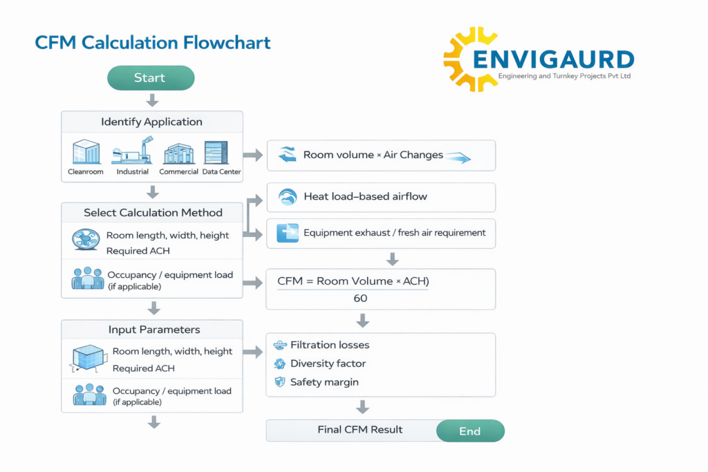
CFM Calculator: How To Calculate CFM? (CFM Calculation + Charts)
CFM Calculator
If you want to know how to calculate cfm in HVAC, here are the two methods.
In the first method, you need to calculate the airflow requirements of the space. It is based on the frequency and size of the room where the air will spread. Another method is calculating the capacity of the system based on its power. It is measured in the form of tons.
Let us find out about both in detail:
Calculating Ventilation Requirements for a Room
The frequency of change in the air per hour is different in different rooms. For example, a room having dangerous fumes need a frequent air change system. A kitchen needs a system that can change the air every three minutes.
Hence, here the CFM calculation involves the below formula:
Required airflow in CFM= total volume of the space / the air exchange interval
Room’s Volume= length multiplied by height and width and measured in feet.
For example, take a rectangular kitchen with an 8-foot ceiling, a room width of 10 feet, and a length of 20 feet.
The volume of the room comes out to be 1,600 cubic feet. If the air exchange interval is three minutes, the CFM comes out as 533 CFM (1600/3).
Calculation Based on System Output
CFM per square foot leads to the measurement of the airflow capacity of an HVAC unit. It helps identify whether the unit is big enough for the ducts and the space.
Here first need to find how much output there is per unit in tons.
1 ton = 12,000 British thermal units (BTUs)
An average output of an HVAC unit is 400.
Let us calculate this for a 10-ton HVAC unit. It serves a 2,000-square-foot building.
Airflow will be 10 tons x 400/2,000 = 2 CFM per square foot.
If the kitchen is 100 square feet, 400 CFM airflow is enough. This would not be enough for a 400 square feet kitchen.
CFM Calculation:
For example, there is a 300-square-foot bedroom. If you need to convert all air two times per hour/ every 30 minutes, how much CFM is required for such a room?
Here is the calculation.
Room Volume= 300 sq ft x 8 ft = 2,400 ft3.
To make it two times per hour (ACH = 2), we need to deliver 4,800 ft3 per hour. CFM is an ‘ft3 per minute unit. Hence, if you divide the total volume by 60, you will get 80 CFM.
Connect with industrial blower manufacturers if you want a blower with the right CFM.
CFM Airflow Calculator
Input the area of room/space, ceiling height, and air changes per hour. The calculator will give the required CFM as an answer.
Total Area (Sq Ft):*
Ceiling Height (In Ft):*
Wanted Air Changes Per Hours (ACH):*
Calculated airflow (CFM):
CFM Calculator: How To Calculate CFM For A Room? (Solved Example)

For example, there is a 1,000 sq ft room with a ceiling of 8 ft height. Let us calculate the CFM of a fan exchanging all the air in such a room every 15 minutes (ACH = 4).
There are two ways to calculate fan CFM:
- Use the CFM formula.
- Use the room CFM airflow calculator Below.
First Method CFM Formula:
- Total Area (Sq Ft): 1000
- Ceiling Height (In Ft): 8
- Wanted Air Changes Per Hours (ACH):4
- Calculated airflow (CFM): 533
- Second Method:
- CFM = (Area x Height x ACH) / 60
- Add the figures.
- CFM = (1,000 sq ft * 8 ft * 4) / 60 min = 533 ft3/min = 533 CFM
- CFM Chart For Common Room Sizes
With the help of the CFM calculator, it is easy to calculate the airflow of various rooms. To help you out, here is an HVAC CFM chart mentioning the CFM for most common room sizes:
CFM Calculator
| Room Size | CFM (At 2 ACH) |
|---|---|
| CFM for a 100 sq ft room | 27 CFM |
| CFM for a 200 sq ft room | 53 CFM |
| CFM for a 300 sq ft room | 80 CFM |
| CFM for a 400 sq ft room | 107 CFM |
| CFM for a 500 sq ft room | 133 CFM |
| CFM for a 600 sq ft room | 160 CFM |
| CFM for a 700 sq ft room | 187 CFM |
| CFM for a 800 sq ft room | 213 CFM |
| CFM for a 900 sq ft room | 240 CFM |
| CFM for a 1000 sq ft home | 267 CFM |
| CFM for a 1500 sq ft home | 400 CFM |
| CFM for a 2000 sq ft house | 533 CFM |
| CFM for a 2500 sq ft house | 667 CFM |
Calculating the Cubic Feet per Minute (CFM) of a Fan
Determining the CFM of a fan is crucial for ensuring adequate ventilation and airflow in various settings. The method chosen depends on the available data and the specific application. Below are several approaches to calculate CFM:
1. Using Room Dimensions and Desired Air Changes per Hour (ACH):
This method is particularly useful when designing ventilation for a specific space:
CFM=(Area×Height×ACH)/60
Where:
- Area = Room’s floor area (square feet)
- Height = Ceiling height (feet)
- ACH = Desired air changes per hour
Example:
For a room measuring 200 sq ft with a ceiling height of 10 ft, requiring 4 ACH:
CFM=(200 sq ft×10 ft×460)=133.33 CFM
This calculation ensures the room receives the appropriate amount of ventilation based on its volume and usage.
2. Using Fan Diameter and Air Velocity:
If the fan’s diameter and the air velocity are known, CFM can be estimated as follows:
CFM=Velocity (FPM)×Area (sq ft)
Where:
- Velocity (FPM) = Air velocity in feet per minute
- Area (sq ft) = Cross-sectional area of the fan (square feet)
For a round fan:
Area=π×(Diameter (ft)2)2
Example:
A fan with a diameter of 2 ft and an air velocity of 600 FPM:
Area=3.1416×(22)2=3.1416 sq ft
CFM=600×3.1416=1,884.96 CFM
This method provides an estimation of the airflow based on physical dimensions and measured airspeed.
3. Using Fan Power and Pressure:
When the fan’s power consumption and the pressure it generates are known:
CFM=(Power (W)Pressure (Pa))×2118.88
Where:
- Power (W) = Fan’s power input in watts
- Pressure (Pa) = Static pressure in pascals
- 2118.88 = Conversion factor from cubic meters per second to CFM
Example:
For a fan consuming 500 W and generating 250 Pa:
CFM=(500250)×2118.88=4,237.76 CFM
This approach links the electrical and mechanical performance of the fan to its airflow capacity.
4. Using Fan Speed (RPM) and Blade Characteristics:
If the fan’s rotational speed and blade pitch are known:
CFM=Fan Area (sq ft)×Air Velocity (FPM)
Where the air velocity can be estimated based on the fan’s RPM and blade pitch.
Note: This method requires detailed knowledge of the fan’s blade design and is often used for more precise engineering calculations.
Considerations:
- Efficiency: Real-world factors such as system resistance and fan efficiency can affect actual CFM. It’s advisable to consult manufacturer data or conduct field measurements for accurate assessments.
- Environmental Factors: Air density, temperature, and altitude can influence airflow and should be considered in critical applications.
For precise calculations and optimal performance, especially in specialized environments, consulting with HVAC professionals or referring to specific fan performance curves provided by manufacturers is recommended.
How Many CFM Per Square Foot?
It is quite a common question. It is related to the ceiling height and ACH. If we take an 8 ft ceiling height, below is the CFM per sq ft for different values of ACH:
- 0.13 CFM per square foot at ACH = 1.
- 0.27 CFM per square foot at ACH = 2.
- 0.40 CFM per square foot at ACH = 3.
- 0.53 CFM per square foot at ACH = 4.
- 0.67 CFM per square foot at ACH = 5.
Duct Diameter CFM Chart
For those using hvac duct CFM calculator, you also need to know the duct diameter to achieve the airflow.
Example: For a 300 CFM airflow, one needs a 10-inch flex duct diameter.
For the right ductwork size, check the below CFM sizing chart:
| Flex Duct Diameter | CFM (Airflow) |
|---|---|
| 4-inch | 20 CFM |
| 5-inch | 50 CFM |
| 6-inch | 80 CFM |
| 7-inch | 120 CFM |
| 8-inch | 170 CFM |
| 9-inch | 230 CFM |
| 10-inch | 300 CFM |
| 12-inch | 500 CFM |
| 14-inch | 740 CFM |
| 16-inch | 1050 CFM |
| 18-inch | 1400 CFM |
| 20-inch | 1875 CFM |
Airflow Units Like L/Min Or Cubic Meters Per Hour
CFM, mainly applied in the US, is an imperial unit. If you are using other units, such as l/min or m3/h, below is the formula to convert those units into CFM.
- 1 CFM = 1.699 m3/h
- 1 CFM = 28.317 l/minute
Conclusion
The professionals consider many factors while determining the right HVAC system for the room. CFM airflow calculator template is useful in providing the right recommendations. Connect with Envigaurd hvac contracting service near you if you are looking to install an HVAC system in your esteemed industry or business infrastructure.
CFM Calculator
Air Flow Calculation Formulas Beyond CFM
CFM is one view of air flow. The formulas below add mass flow, standard versus actual flow, face velocity and orifice flow, followed by three worked use cases from pharmaceutical, painting and chilled-water systems.
Table 1: Core Air Flow Calculation Formulas
| Formula Name | Equation | Variable Definitions | Application Context |
|---|---|---|---|
| Volumetric Flow Rate (Velocity Area Method) | Q=A×v | Q = Flow Rate (m³/s or ft³/min) A = Cross-sectional Area (m² or ft²) v = Air Velocity (m/s or fpm) | Basic duct air flow calculation and pipe sizing. |
| Mass Flow Rate | m˙=ρ×Q | m˙ = Mass Flow Rate (kg/s) ρ = Air Density (kg/m³) Q = Volumetric Flow Rate (m³/s) | Engine mass air flow calculation, compressed air systems, and HVAC psychrometrics. |
| Standard vs. Actual Flow | Qact=Qstd×PactPstd×TstdTact | P = Absolute Pressure (Pa or psi) T = Absolute Temperature (K or R) | Compressor air flow calculation and altitude corrections. |
| Pitot Tube / Differential Pressure | v=ρ2×ΔP | ΔP = Velocity Pressure (Pa) ρ = Density (kg/m³) | Air flow calculation from differential pressure and traverse readings. |
| Fan Law 1 (Affinity Law) | Q2Q1=N2N1 | Q = Flow Rate N = Fan Speed (RPM) | Fan air flow calculation for speed modulation. |
| Pressure Drop (Darcy-Weisbach Simplified) | ΔP=f×DL×2ρv2 | f = Friction factor L = Length (m) D = Diameter (m) | Air flow calculation through duct and pipe systems. |
System Design and Ductwork Dynamics
Accurate air flow calculation in duct systems is a multi-variable problem. In the pharmaceutical industry, for instance, we do not merely move air, we control turbulence to prevent particle contamination. When performing a duct air flow calculation formula application, one must determine the friction rate per unit length. This requires analyzing the duct material roughness and the aspect ratio of rectangular ducts.
Furthermore, air flow calculation through duct necessitates a careful balance of static pressure and dynamic pressure. As air velocity increases, the static pressure drops. A high-velocity system saves space but incurs significant noise and energy penalties, whereas a low-velocity system is quieter but requires larger ducts. This trade-off is critical in commercial HVAC air flow calculation where building architectural constraints often conflict with acoustical requirements.
Similarly, air flow calculation in pipe for compressed air systems involves dealing with high pressures (often exceeding 7 bar). Here, the ideal gas law deviations become significant, and we must account for the compressibility factor. A precise compressed air flow calculation formula is essential to determine the pressure drop between the compressor and the point of use, ensuring that pneumatic tools receive the necessary pressure for optimal operation.
Advanced Measurement and Pressure Based Calculations
In the field, direct measurement of velocity is not always feasible. Consequently, Envigaurd engineers frequently rely on air flow rate calculation using pressure. By using a differential pressure sensor across an orifice plate, venturi meter, or even the coil of an AHU, we can derive the flow rate.
The air flow calculation based on pressure is derived from Bernoulli’s principle. When the flow area constricts, the velocity increases and the pressure decreases. By measuring this pressure differential (
ΔP), we can calculate the flow. This method is standard for air flow measurement calculation in existing building retrofits where installing hot-wire anemometers in every duct is impractical.
For critical environments like fume hoods, the air flow calculation from differential pressure is used for continuous monitoring. We monitor the face velocity by measuring the pressure differential across the hood sash. Any deviation triggers an alarm, ensuring that containment is not compromised during the fume hood air flow calculation process.
Ventilation Strategies and Industrial Applications
Ventilation and Containment The objective of air flow calculation for ventilation varies by sector. In a commercial office, it is about CO2 dilution and thermal comfort. In a paint mixing room or a spray booth, it is about maintaining a minimum velocity to keep volatile organic compounds (VOCs) suspended in the exhaust stream.
A spray booth air flow calculation requires determining the cross-sectional area of the booth face and applying a specific capture velocity, typically 0.5 m/s to 1.0 m/s, depending on the toxicity of the solvents used. Similarly, a kitchen hood air flow calculation utilizes thermal plume equations to determine how much heat and grease-laden air the hood must capture.
Confined Space Safety For confined space air flow calculation, the stakes are life and death. We calculate the volume of the space (e.g., a tank or vessel) and determine the air changes required per hour to purge hazardous gases. This involves calculating the required CFM of a portable blower to achieve a specific number of air changes within a set time frame before entry is permitted.
Cooling and Thermal Management In industrial cooling, the cooling tower air flow calculation is vital for the thermodynamic cycle. The tower must reject the heat load from the chiller or process. The cooling tower fan air flow calculation determines the volume of ambient air drawn across the fill media to facilitate evaporative cooling. If the cooling tower air flow rate calculation is inaccurate, the approach temperature will widen, leading to inefficient process cooling.
Similarly, a radiator air flow calculation for engine cooling or a cooling fan air flow calculation for electronics ensures that the heat transfer coefficient is sufficient to maintain junction temperatures or engine coolant temperatures within safe limits. These calculations often involve CFD (Computational Fluid Dynamics) modeling to ensure that the air flow is effectively directed over the hot surfaces rather than bypassing them.
Rotating Equipment: Fans, Blowers, and Compressors
Selecting the correct moving equipment is the culmination of the preceding calculations.
Fan Selection When performing a fan air flow calculation, we generate a system curve that plots the required pressure drop against various flow rates. We then select a fan whose performance curve intersects the system curve at the desired operating point. For FD fan air flow calculation (Forced Draft), we must account for the pressure drop across the boiler bed and the superheater elements.
An axial fan air flow calculation differs significantly from a centrifugal fan. Axial fans are efficient for high volume and low pressure applications (like cooling towers), whereas centrifugal fans are used for higher pressure systems (like dust collectors). The air flow fan calculation must match the fan type to the system impedance.
Blowers and Compressors A blower air flow rate calculation typically involves positive displacement machines. Here, the flow is largely a function of speed and rotor volume, with minor slip losses. This is distinct from dynamic compressors.
An air compressor flow rate calculation is critical for specifying the machine size. We sum the peak demands of all tools, adding a diversity factor, to arrive at the Free Air Delivery (FAD) required. An inaccurate compressor air flow calculation can lead to insufficient pressure drop during production spikes, causing costly downtime.
Technical Use Cases and Calculated Examples
To illustrate the practical application of these methodologies, let us examine three specific technical use cases encountered in recent Envigaurd projects.
Use Case 1: Pharmaceutical Isolator Face Velocity
Scenario: A Glove Box Isolator in a sterile injectable facility requires a negative pressure cascade. Objective: Perform an exhaust fan air flow calculation to maintain a containment of 100 Pascals negative pressure relative to the room, while maintaining an inflow velocity of 0.5 m/s through the open glove ports.
Parameters:
- Total leakage area (gloves, ports) = 0.08 m²
- Target inflow velocity (v) = 0.5 m/s
- Internal volume = 1.5 m³
- Desired ACH = 20 (for particulate control)
Calculation:
- Inflow Requirement (Volumetric): Q=A×v Q=0.08 m2×0.5 m/s=0.04 m3/s Converting to CMH: 0.04×3600=144 CMH
- ACH Requirement (Volumetric): Q=Volume×ACH Q=1.5 m3×20 hr−1=30 CMH
- Fan Sizing: The governing factor is the higher of the two values. Therefore, the exhaust fan must be sized for 144 CMH. However, to maintain the negative pressure of 100 Pa, the fan must overcome this resistance. We select a fan capable of generating 144 CMH at a static pressure of at least 150 Pa (safety factor applied).
Use Case 2: Industrial Spray Booth Exhaust
Scenario: An automotive spray booth requires exhaust to remove paint overspray. Objective: Conduct a spray booth air flow calculation to ensure cross-draft velocity.
Parameters:
- Booth dimensions: Width = 4m, Height = 3m, Length = 10m
- Required cross-draft velocity = 0.6 m/s
- Filter resistance (dirty) = 250 Pa
- Dwork static pressure loss = 100 Pa
Calculation:
- Air Flow Rate (Q): Cross-sectional area (A) facing the airflow = Width × Height = 4×3=12 m2 Q=A×v Q=12 m2×0.6 m/s=7.2 m3/s In CMH: 7.2×3600=25,920 CMH
- Static Pressure Requirement: Total Static Pressure = Filter Loss + Duct Loss + Entry Loss TSP=250+100+50 (estimated entry)=400 Pa Result: The axial fan selection must be capable of moving 25,920 CMH against a static pressure of 400 Pa.
Use Case 3: Orifice Plate Flow Measurement (Chilled Water AHU)
Scenario: Verifying the airflow of a large Air Handling Unit (AHU) using an orifice plate located in the main supply duct. Objective: Perform an air flow rate calculation using pressure.
Parameters:
- Differential Pressure reading (ΔP) = 75 Pa
- Air Density (ρ) = 1.2 kg/m³ (standard conditions)
- Discharge Coefficient (Cd) for orifice plate = 0.61
- Orifice Area (A) = 0.5 m²
Calculation:
- Velocity Calculation: v=Cd×ρ2×ΔP v=0.61×1.22×75 v=0.61×125 v=0.61×11.18≈6.82 m/s
- Flow Rate Calculation: Q=A×v Q=0.5 m2×6.82 m/s=3.41 m3/s In CMH: 3.41×3600≈12,276 CMH This air conditioning air flow calculation allows the commissioning engineer to balance the system against the design specs.
Conclusion
The discipline of air flow calculation is a rigorous field that integrates physics, fluid mechanics, and practical engineering constraints. From the mass air flow calculation needed for internal combustion engines to the precise ridge vent air flow calculation required for passive building cooling, the principles remain constant while the application demands evolve.
At Envigaurd, our approach combines these fundamental formulas with advanced measurement techniques and industry-specific standards. Whether executing an exhaust air flow rate calculation for a high-rise kitchen or a louver air flow calculation for a power plant intake, the reliance on accurate data ensures system integrity, energy efficiency, and operational safety. By mastering these calculations, engineers ensure that the invisible medium of air is controlled effectively to serve the tangible needs of modern industry.